"Hacking" an NES Pad to work with a Pocket PC
I use my Pocket PC quite a bit for games, mainly old NES titles on
the PocketNester emulator. But the hardware buttons on the
iPAQ are too small, and it can be hard to use certain combinations.
My solution for this was to interface an original Nintendo
controller to my PPC.
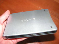
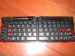
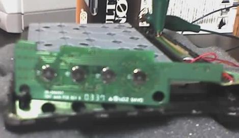
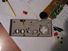
For this mod, I used a cheap IR keyboard (Belkin
F8U1500) and wired the directional keys and PPC hardware
buttons (circled below) directly to the NES.
Step 1: Install the KB software on your
handheld. Make sure you can use the keyboard to control your
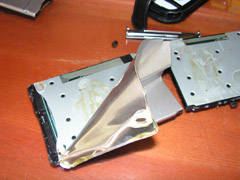
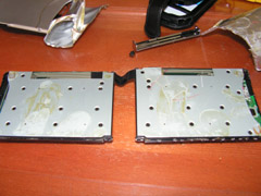
game. Dismantle the Belkin IR Keyboard. Now this
was the most frustrating part. There are no screws on the
keyboard housing, you'll have to pry the aluminum casing off with a
screwdriver and peel it back manually. Be careful with the
right half (the one with the battery holder and IR port), it
contains the main circuit board. You can cut the ribbon cable
in the middle if it's in the way, we won't need it.
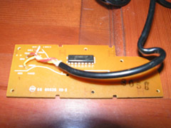
Step 2: Remove the circuitry from the keyboard, you won't need
the flexible circuit under the keys, just the PCBs.
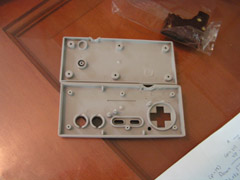
Step 3: Dismantle your Nintendo controller. Remove the
circuit board and desolder the wires and the IC on the back.
 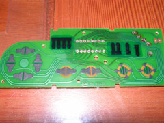
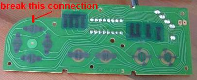
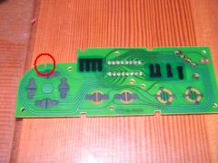
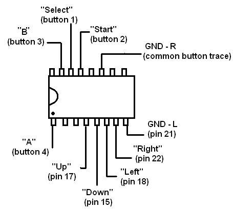
Step 4: Each of the controller's buttons are connected to a
common ground, and a different pin on the IC. You'll need to
break this common connection so that the buttons on the D-pad are
separated from the Start, Select, A, and B buttons. The
easiest way to do this is to dremel out the trace near the top.
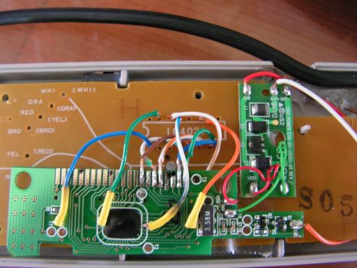
Step 5: Now you'll need to map out where the buttons on the
keyboard lead. There are 22 pins on the Belkin circuit board
that connect to the flexible circuit. Each key connects two
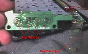
different pins. The buttons on the KB that correspond to the
four hardware buttons on the iPAQ do not connect to these pins.
Remove the tape on the back side of the board and you'll see the
contacts for those buttons on the board. All four of these
buttons are connected to each other by a common trace. If
you're using a different keyboard, you'll have to either test the
pins one by one and see what appears on your PDA (what I did), or
tone out the circuit (what I should have done). For the
purpose of this tutorial, Pin 1 is on the bottom and Pin 22 on the
top.
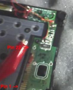 
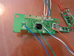
Step 6: It's time to wire the Belkin board to the NES board.
The pins combos that correspond to the arrow keys on the KB are: 15
& 21 (down), 17 & 21 (up), 18 & 21 (left), and 22 & 21 (right).
Since they all have a common pin, we can wire them directly to the
NES board. The hardware buttons also have a common trace
(solder straight to the pads under the buttons), and we'll be able
to wire them directly now that we've separated the GND trace on the
NES controller board.
 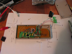
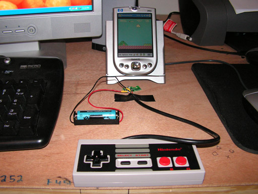
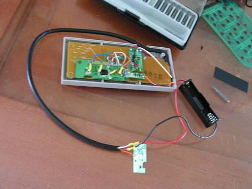
Step 7: Add a switch to the circuit if you like, and dremel
out some space in the casing so that it closes neatly. Extend
the flimsy wires connected to the IR transmitter and the battery, so
they are outside the case. I was originally planning to keep
the IR transmitter and battery inside the NES case, but this made it
impractical to use since it had to be ridiculously close to the iPAQ
to work, and you would have to open the case to change the button
cell battery.
Step 8: Put the cover back on and test it with your favorite
emulator, or PPC game!
Email me:

|